My First Scenario
Find an activity in left-hand side menu (Wizlink® Activities toolbox) or start to write its name in the text box on the top of this toolbox (where greyish text Search by activity name is seen). Then drag it and drop on the Flowchart.
To build a scenario you have to connect selected activity boxes one with another, starting from the button Start. When you hover your mouse over the activity box you can see 4 (or more) adjustment handles. Click one of them and drag it to another activity box and then drop it on any of adjustment handles that are around the second activity box. Thus you create an arrow. The arrowhead indicates the course of the scenario.
You can also drop chosen activity (from Wizlink® Activities toolbox) directly on a big arrowhead that appears around preceding activity box in scenario, when you drag one activity towards another. The arrow between two activities is drawn at once in this case.
There are few activities where the action flow is determined by internal structure of activity and no arrows are required (e.g. inside the Sequence activity).
Arrange chosen activities on the flowchart clearly in order of execution.

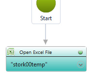
1. Active scenario – activity is connected to button Start with an arrow. After pressing <F5> key this scenario starts running.
Every activity box contains a button in its top right corner. When the activity box is part of a scenario this button:
-
- may be green – it informs that no error warnings are inside the box and scenario is ready to run;
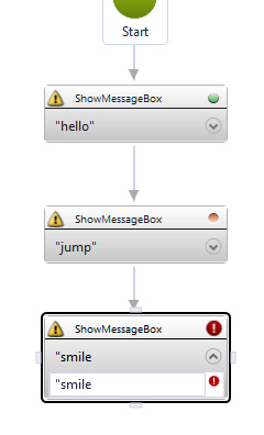
- may be orange - when you want to separate an activity box from the scenario, but do not want to remove it completely (e.g. when testing something) – click on that button to make it orange.
- may be red – a button turns into bigger red circle (with white exclamation mark inside), when there are some error warnings and the scenario will not run. Much smaller red circle appears also to the right of that field, in which problem occurs.
In this last case big red circle sign (like Do Not Enter road sign) appears simultaneously on the button Run scenario in the toolbar, as well as on the right side of the Main Scenario Flowchart title bar and any grouping activity superior to that activity with error. Third bar Errors appears at one time at the bottom of the screen, below Variables and Scenario Invoker Parameters. Check there a brief information about an error.

2. Wizlink® scenario – the second activity is disconnected (orange dot in upper right corner), the third activity is wrong. To make it right you need to write down the lacking part of double quotes. Your corrected scenario will display the blue box with the word hello, then after clicking the OK button (or pressing Enter) the scenario will display next blue box with word smile. Below: Run scenario button informing about an error in the scenario and Errors bar.

The Run scenario button with Do Not Enter sign appears also while the scenario is running and Wizlink® is busy.
While the scenario is running, the fields that may affect the shape of the scenario are locked for editing: it is not possible to add activities or remove them from the flowchart, dropping controls on activities already in the scenario does not work, one cannot edit the properties. Operations on variables are, in fact, possible (like declaring, removing or editing), but it has no effect whatsoever to the running scenario. After the end of the scenario the variable state is restored to the one before the project was launched.
These rules apply to both main scenario and alternative scenario.
If an attempt is made to close Wizlink® during the execution of the scenario, the program will display a dialog box for user decision. While displaying this window on the screen, the robot does not stop its work.
Each activity have to be parameterized. Use the toolbox on the right side of the screen. When you click on the activity its properties are displayed. They are optional or required. If you do not fill all the required properties, the error symbol will appear. The red symbol is always shown in order of occurrence of errors.
There might be four properties group: Input, Output, Misc and Settings. Available values are text, variable, Boolean, numeric, dropdown and sometimes the checkbox.